GNSS Master Documentation
App Version 1.0.11 May 2023
App Features
GNSS Master app allows you to:
-
Connect to your external GNSS receiver via USB Serial (OTG), Bluetooth, BLE and TCP/IP
-
Send corrections to your GNSS receiver from in-built NTRIP Client (V1 & V2), and PointPerfect
-
Output your GNSS receiver data to NTRIP Server (V1 & V2), TCP Client or TCP Server
-
Use high accuracy position from your receiver directly with SW Maps, and with all other Android apps via Mock Location
-
Change your u-blox/Septentrio receiver configuration to Rover, Base or load any custom configuration file
Installation
The app can be installed from the Google Play Store
Getting Started
When you first open the app, you will be asked to allow certain permissions to GNSS Master.
-
Location Permission
-
Display Notifications
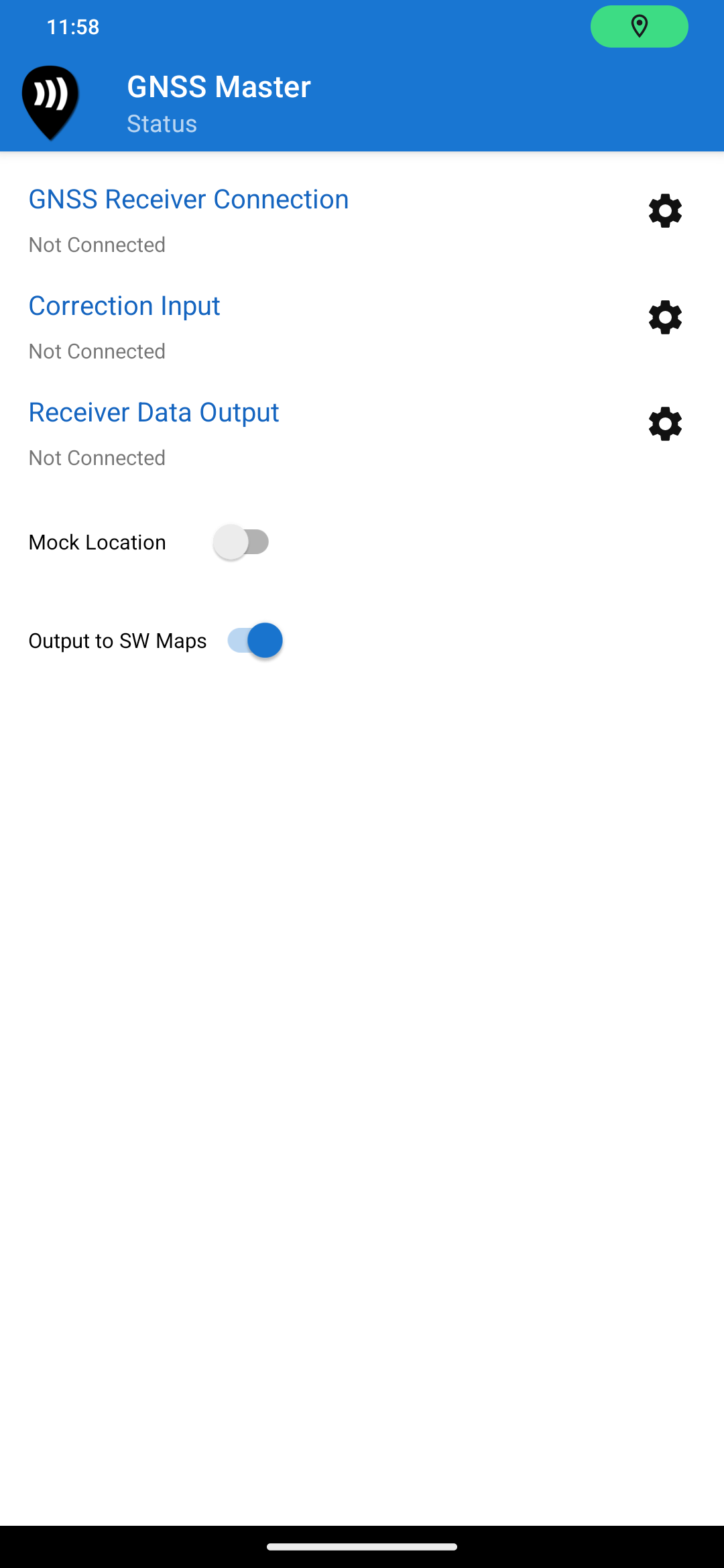
Once you accept the permissions, the Status page will load, showing the current status of the app. The status page shows the current status of the connected streams, and whether Mock Location and SW Maps Link is enabled.
Main App UI
The app operates using three data streams:
-
GNSS Receiver Connects to GNSS receivers using Bluetooth, BLE, USB OTG or TCP/IP
-
Correction Connects to an NTRIP Caster or PointPerfect correction. The received corrections are transferred to the GNSS receiver stream if connected.
-
Data Output Stream Can be a NTRIP Server or TCP Client/Server. The data received from the GNSS Receiver is written to this stream.
All the features of the app are accessible through the left navigation drawer. The drawer can be opened by swiping from the left edge of the screen, or by pressing the GNSS Master icon on the top menu bar.
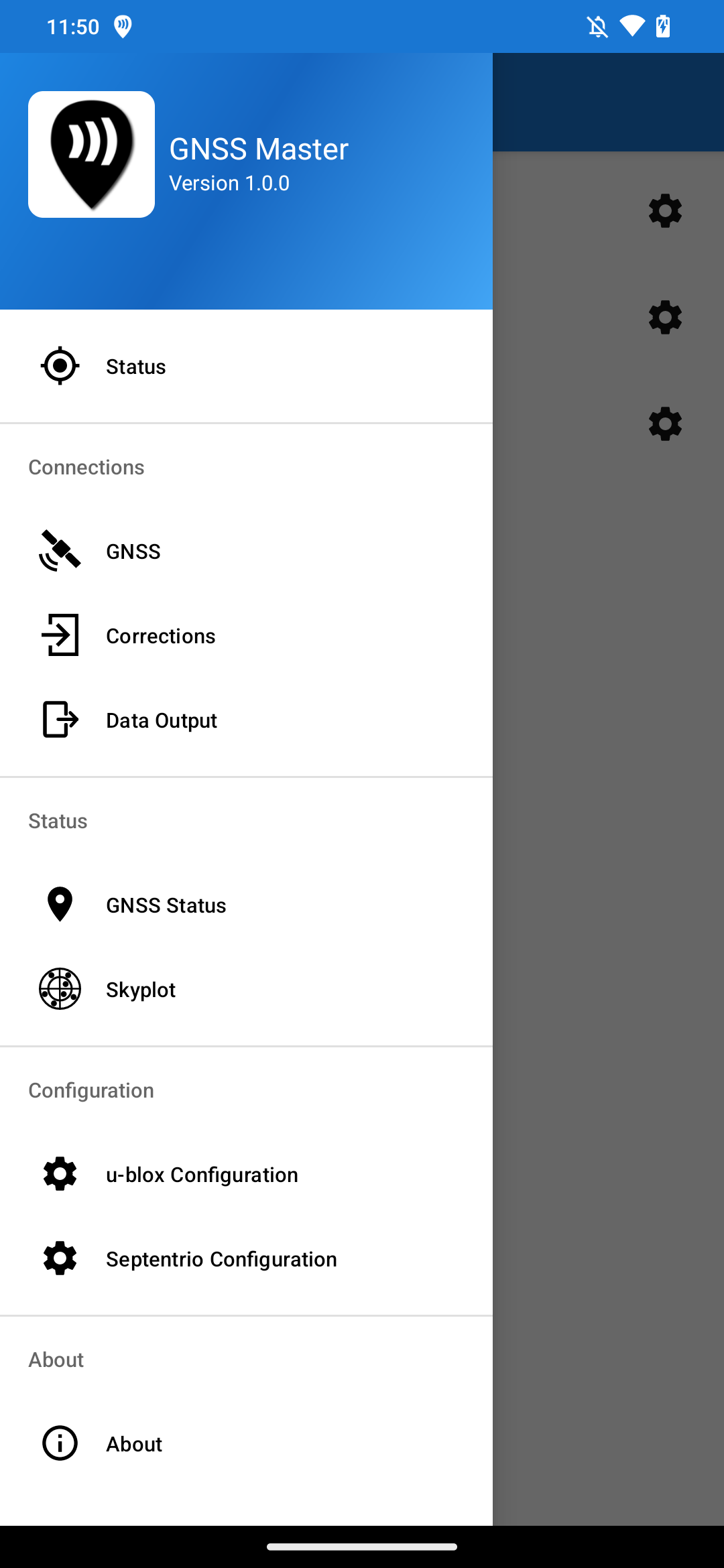
Navigation Drawer
GNSS Receiver Connection
GNSS Master supports connecting to external GNSS receivers via Bluetooth, BLE, USB OTG or TCP/IP.
USB OTG GNSS Connection
To connect a GNSS receiver using USB OTG, follow the steps below.
-
Connect the USB GNSS receiver to your phone or tablet.
-
Open the GNSS Receiver connection page from the navigation drawer.
-
In the Mode dropdown, select USB Serial. The app will list all the currently connected devices.
-
Select the device to connect to. Some devices may have multiple interfaces that connect to different ports on the GNSS receiver.
-
Select the correct baud rate. This step is important if using a UART to USB adapter.
-
Press the Connect button.
Once the receiver is connected, the Status label changes to Connected and the app displays the data rate and total amount of data received.
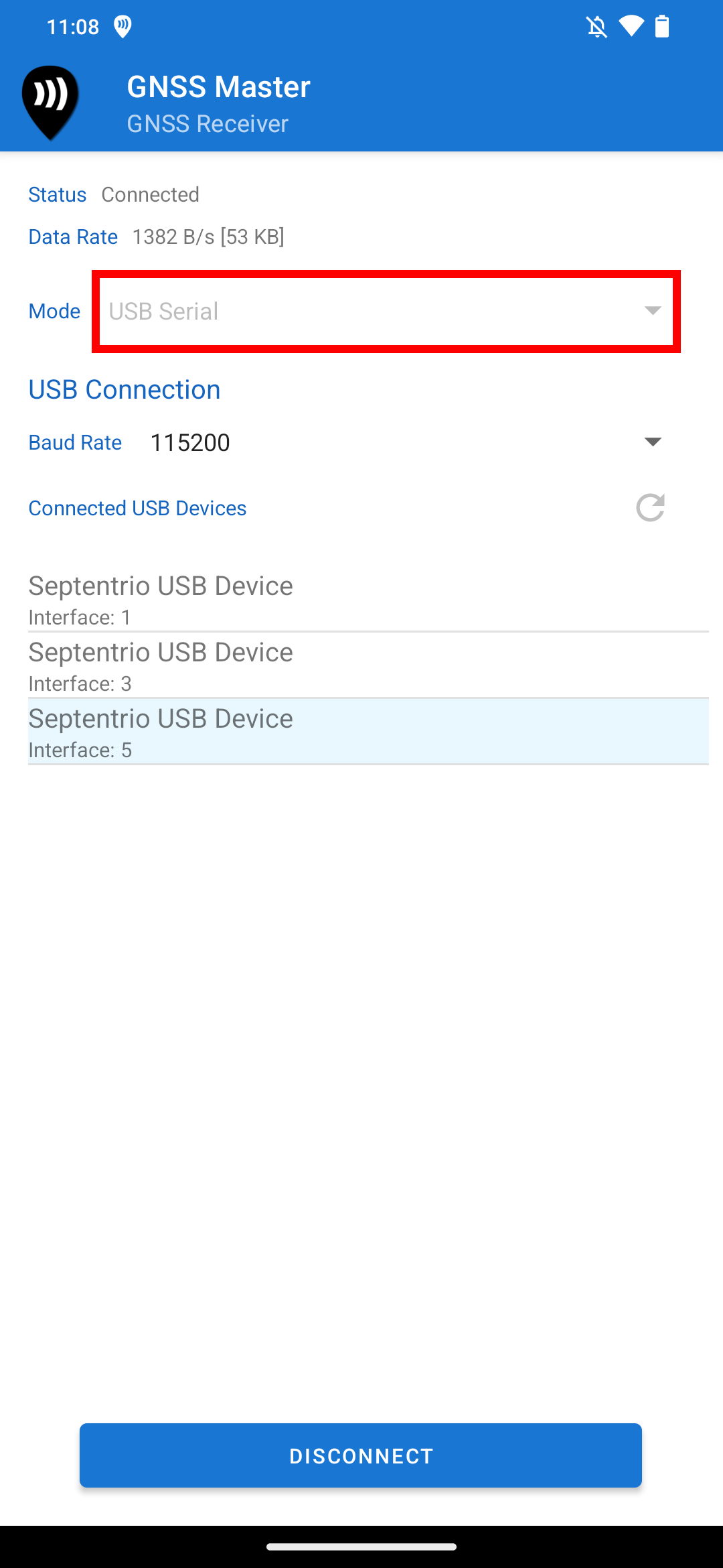
USB GNSS Connection
Bluetooth GNSS Connection
To connect a GNSS receiver using Bluetooth Classic, follow the steps below.
-
Pair the Bluetooth device to your phone or tablet. You may do so using the Bluetooth settings in Android.
-
In GNSS Master Open the GNSS Receiver connection page from the navigation drawer.
-
In the Mode dropdown, select Bluetooth. The app will list all paired Bluetooth devices which support the serial port profile (SPP).
-
Select your GNSS receiver from the list of paired devices and press Connect
Bluetooth Low Energy (BLE) GNSS Connection
To connect a GNSS receiver using Bluetooth Low-Energy (BLE), follow the steps below.
-
Pair the Bluetooth device to your phone or tablet. You may do so using t¬he Bluetooth settings in Android.
-
In GNSS Master Open the GNSS Receiver connection page from the navigation drawer.
-
In the Mode dropdown, select Bluetooth LE. The app will list all paired Bluetooth devices which support BLE serial profile.
-
Select your GNSS receiver from the list of paired devices and press Connect
TCP/IP GNSS Connection
GNSS Master supports connecting to receivers over TCP/IP. The app works as a TCP client, to connect to a remote GNS receiver stream. To connect to GNSS receiver using TCP/IP, follow the steps below.
-
In GNSS Master open the GNSS Receiver connection page from the navigation drawer.
-
In the Mode dropdown, select TCP/IP.
-
Enter the IP Address/domain name and the TCP port number of the GNSS receiver to connect to.
-
Press Connect
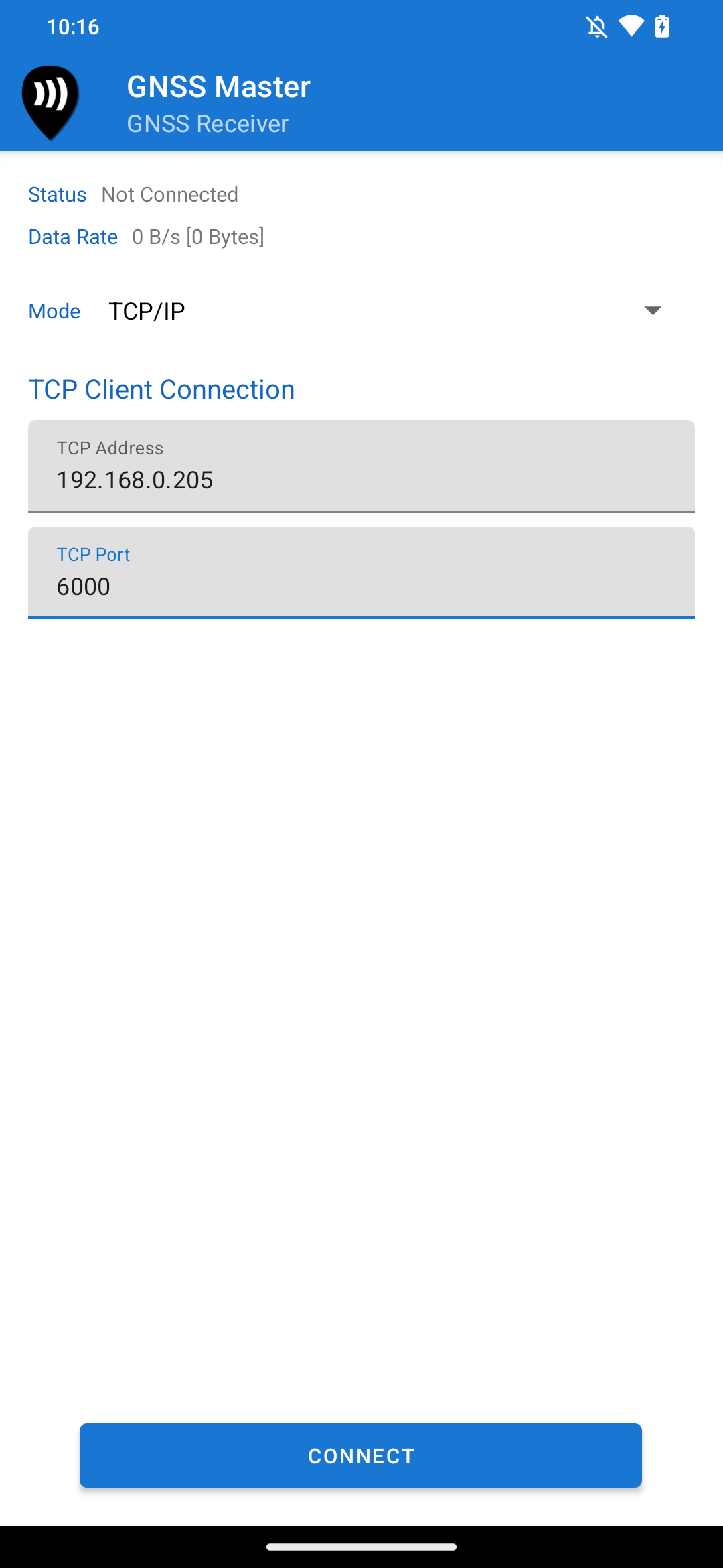
TCP/IP GNSS Connection
Correction Input
GNSS Master supports connecting to NTRIP Casters and PointPerfect to provide correction data input to the connected GNSS receiver.
NTRIP Client
GNSS Master can work as an NTRIP Client to retrieve GNSS correction data from NTRIP casters. Both NTRIP protocols V1 and V2 are supported.
Adding an NTRIP Client Connection Profile
To add an NTRIP Client connection profile, follow the steps below.
-
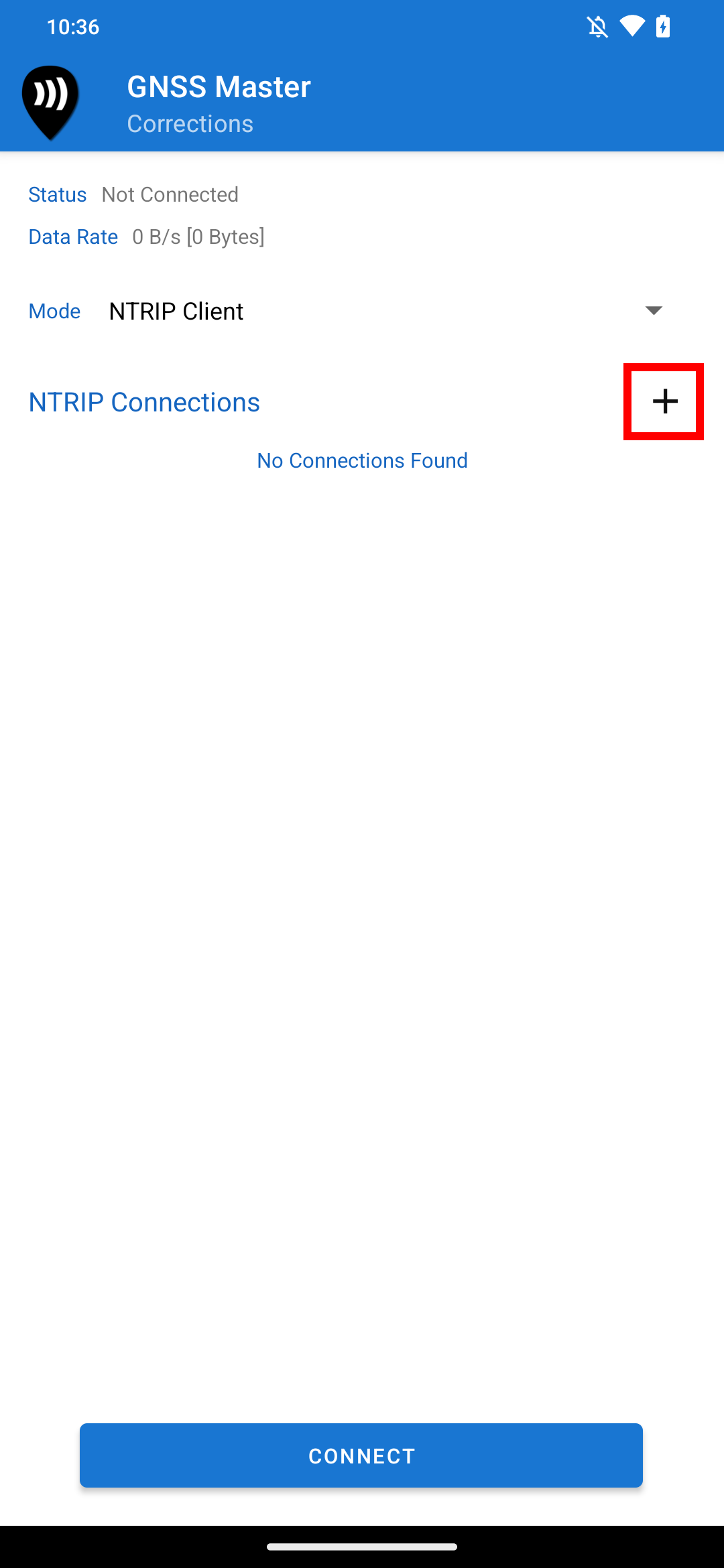
Open the Corrections page.
-
In the Mode dropdown, select NTRIP Client.
The NTRIP Client Correction Page
-
Press the + button to add an NTRIP Connection.
-
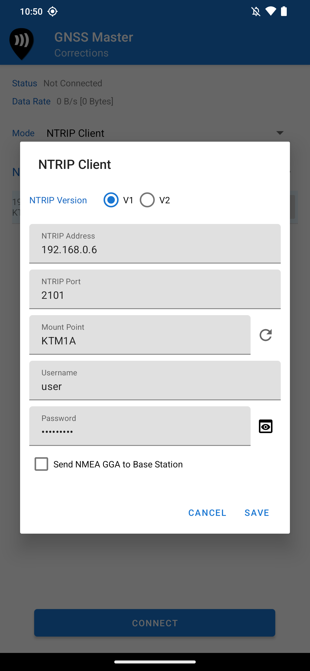
In the NTRIP Client dialog box, select the NTRIP version, and then enter the NTRIP address, port, mount point name, username and password. You can press the button next to the mountpoint input to fetch the NTRIP source table from the caster.
-
Check the option Send NMEA GGA to Base Station if your base stations requires rover coordinates (example: VRS streams).
-
Press Save.
-
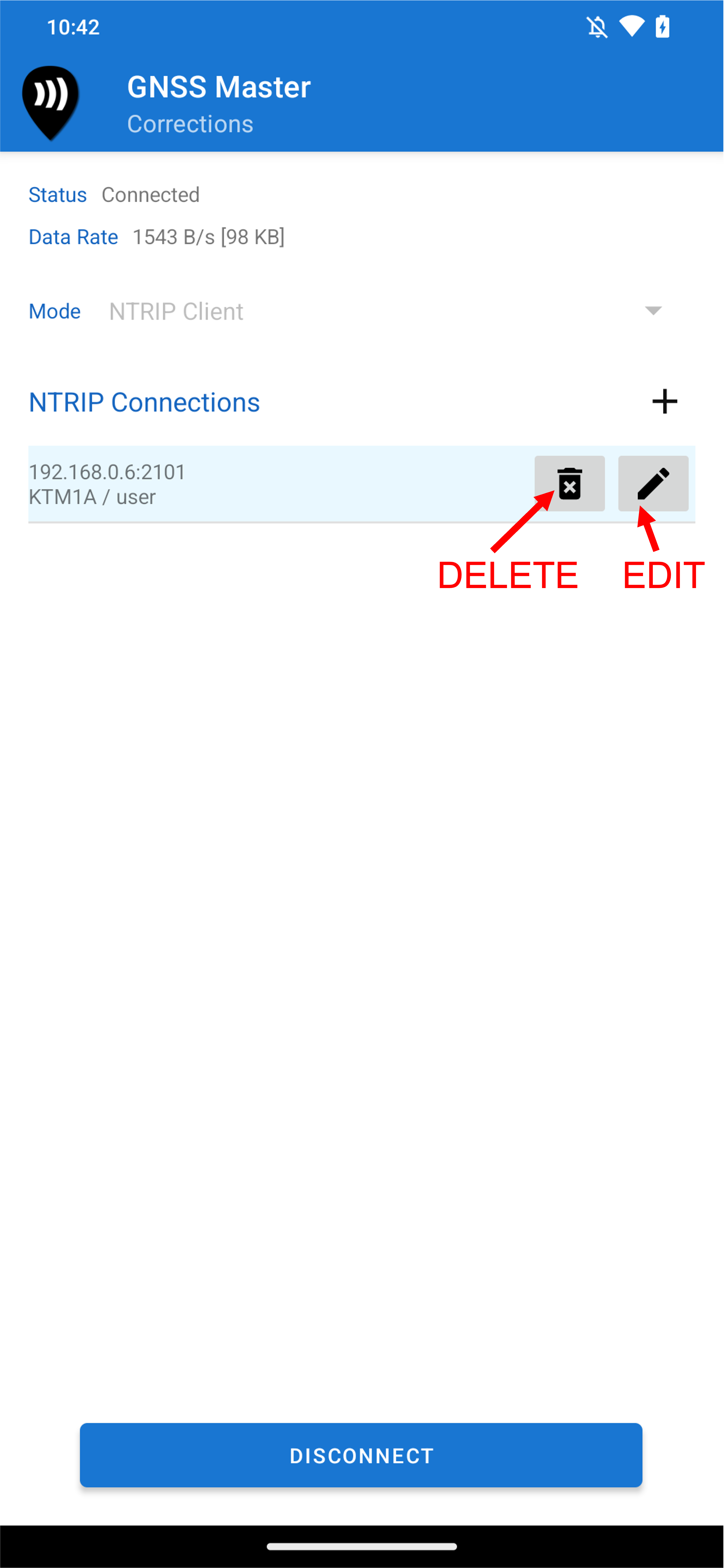
The NTRIP connection should now appear in the connections list.
Adding an NTRIP Client Connection
Connecting to NTRIP
To connect to the NTRIP caster, simply select the profile you wish to use and press the Connect button. You can then disconnect by pressing the Disconnect button.
The NTRIP client connects and stays connected to the caster even when the receiver is not connected. When a GNSS receiver is connected, the data received from the NTRIP stream is written to the GNSS receiver stream.
Editing and Deleting NTRIP Connections
You can press the Delete and Edit icons next to the connection you wish to edit or delete in the list of NTRIP connections.
NTRIP Client List
PointPerfect
GNSS Master can be used as a PointPerfect MQTT Client. The app connects to PointPerfect and retrieves SPARTN corrections, which are then transferred to the GNSS receiver for correction. The app also retrieves the dynamic keys needed for decrypting the SPARTN messages.
Notes:
-
Using PointPerfect requires a GNSS receiver capable of decoding and applying SPARTN corrections. Currently, only u-blox F9P/F9R/F9K receivers are supported
-
You need to obtain a PointPerfect subscription to use this correction service. Subscriptions can be purchased from ArduSimple.
PointPerfect Connection
To connect to the PointPerfect correction service, follow the steps below.
-
Copy your PointPerfect subscription configuration JSON File to your phone or tablet.
-
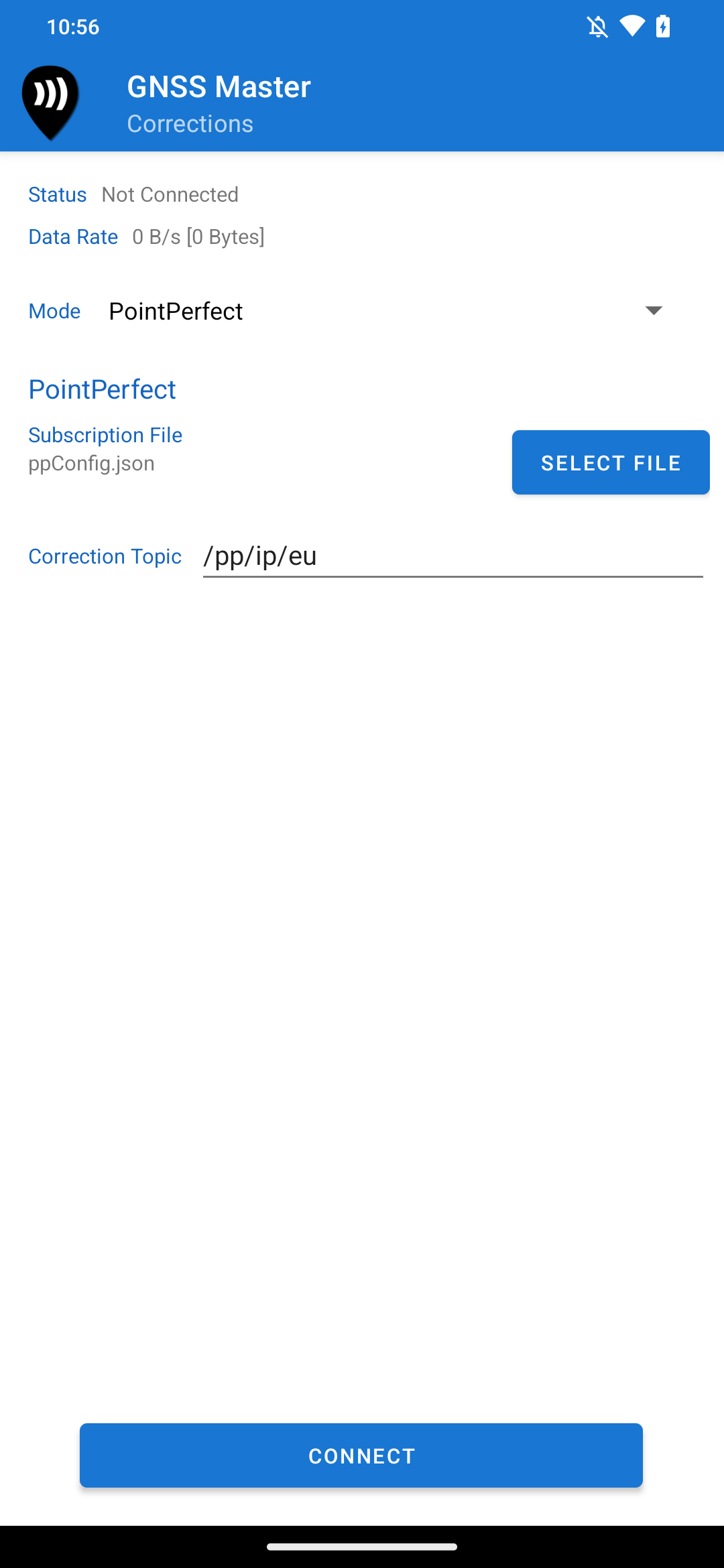
In GNSS Master, Open the Corrections page.
-
In the Mode dropdown, select PointPerfect.
-
Click the Select File button. Then, select your PointPerfect subscription configuration JSON File.
-
Enter the correction topic for your region. Refer to PointPerfect Service Description for more details.
-
Press the Connect button.
Data Output
GNSS Master supports several options for data output. The app writes all the data received from the GNSS receiver into the connected data output stream.
NTRIP Server
GNSS Master can function as an NTRIP server. This option is useful for connecting to a receiver that is set up in base configuration and then sending the correction data to rovers via an NTRIP caster.
Adding an NTRIP Server Connection Profile
To add an NTRIP Server connection profile, follow the steps below.
-
Open the Data Output page.
-
In the Mode dropdown, select NTRIP Server.
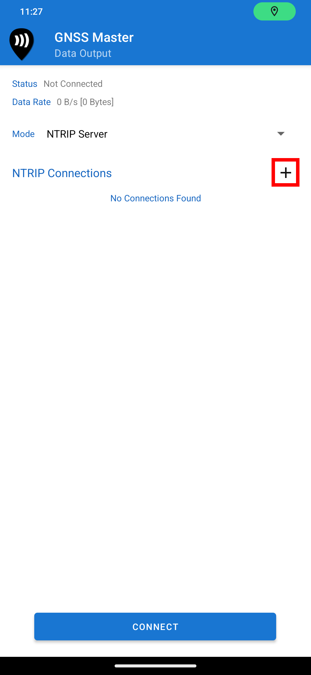
The NTRIP Server Data Output Page
-
Press the + button to add an NTRIP Connection.
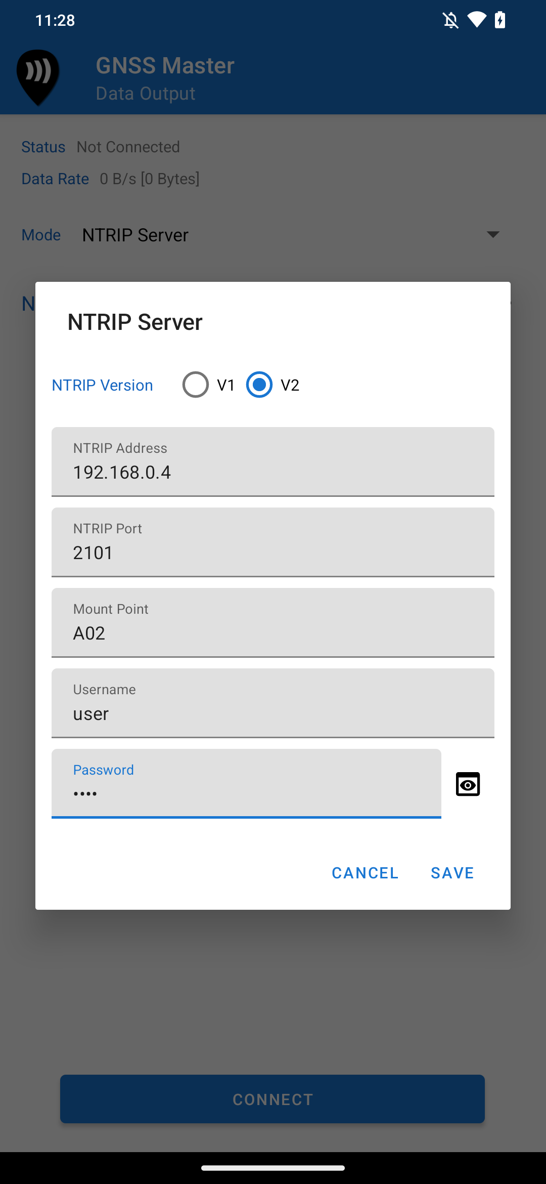
-
In the NTRIP Server dialog box, select the NTRIP version, and then enter the NTRIP address, port, mount point name, username and server password.
-
Press Save.
-
The NTRIP connection should now appear in the connections list.
Adding an NTRIP Server Connection
Connecting to NTRIP
To connect to the NTRIP caster, select the profile you wish to use and press the Connect button. You can then disconnect by pressing the Disconnect button.
The NTRIP server connects and stays connected to the caster even when the receiver is not connected. When a GNSS receiver is connected, the data received from the receiver is written to the NTRIP server stream.
Editing and Deleting NTRIP Connections
You can press the Delete and Edit icons next to the connection you wish to edit or delete in the list of NTRIP connections.
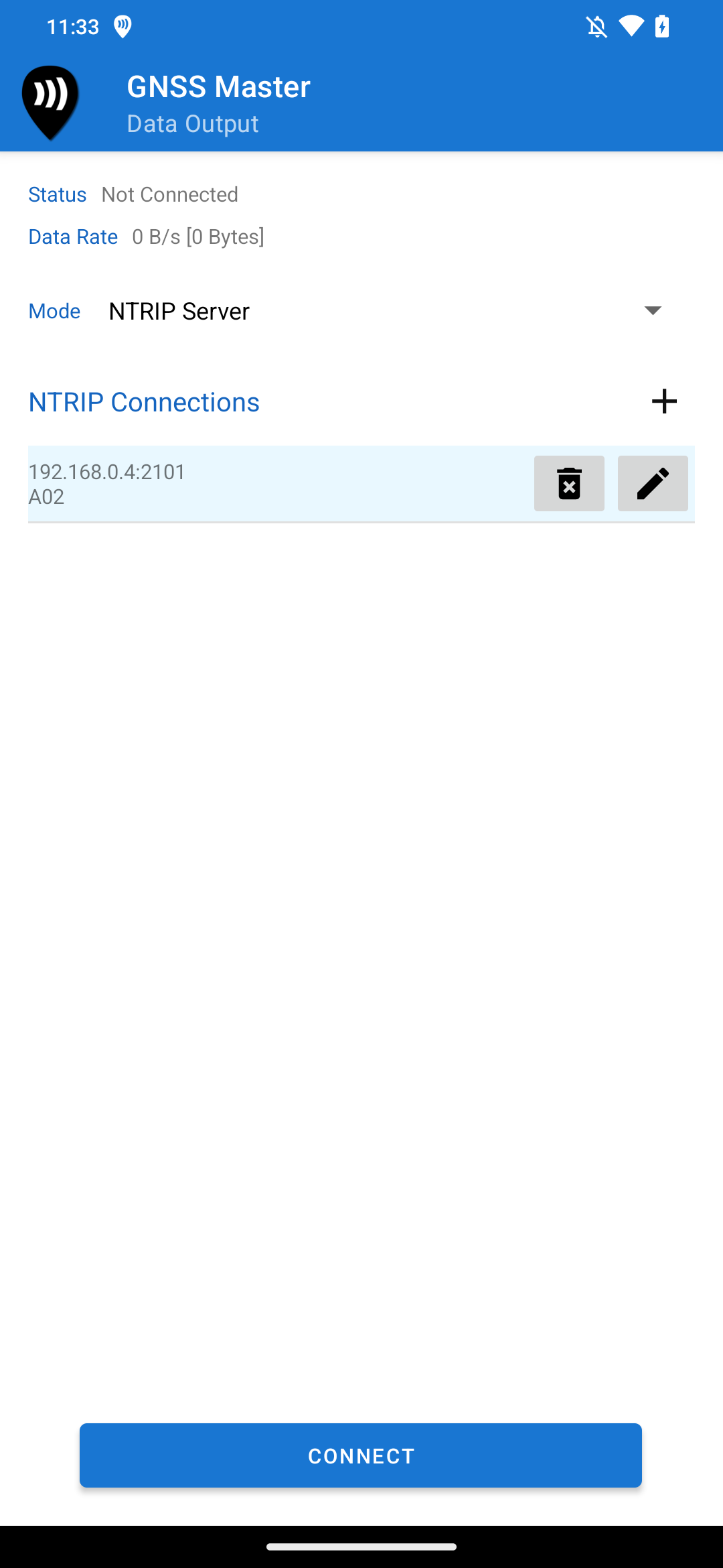
NTRIP Server List
TCP Client
The TCP Client data output stream lets you output the data from the GNSS receiver to a local or remote TCP/IP server. To set up data output, follow the steps below.
-
In GNSS Master open the Data Output Receiver connection page from the navigation drawer.
-
In the Mode dropdown, select TCP Client.
-
Enter the IP Address/domain name and the TCP port number of the TCP server to send data to.
-
Press Connect
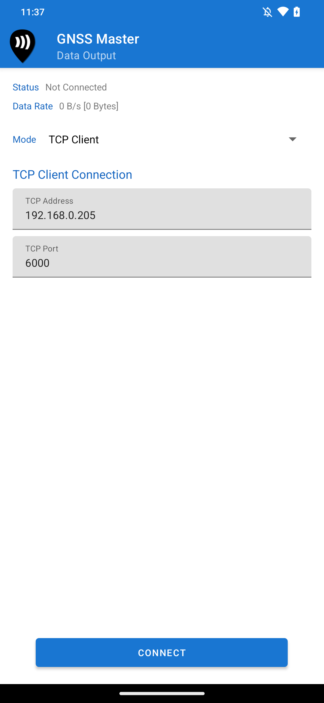
TCP Client Data Output
TCP Server
The TCP Server data output mode turns the app into a TCP server, to which other apps on the same device, or in remote devices can connect to as TCP clients and receive the data from the GNSS receiver connected to GNSS Master. To setup TCP Server data output, follow the steps below.
-
In GNSS Master open the Data Output Receiver connection page from the navigation drawer.
-
In the Mode dropdown, select TCP Server.
-
Enter the TCP port number to listen to.
-
Press Connect
Other apps on the same device can now connect to the TCP server via localhost:port to get data from the connected GNSS receiver.
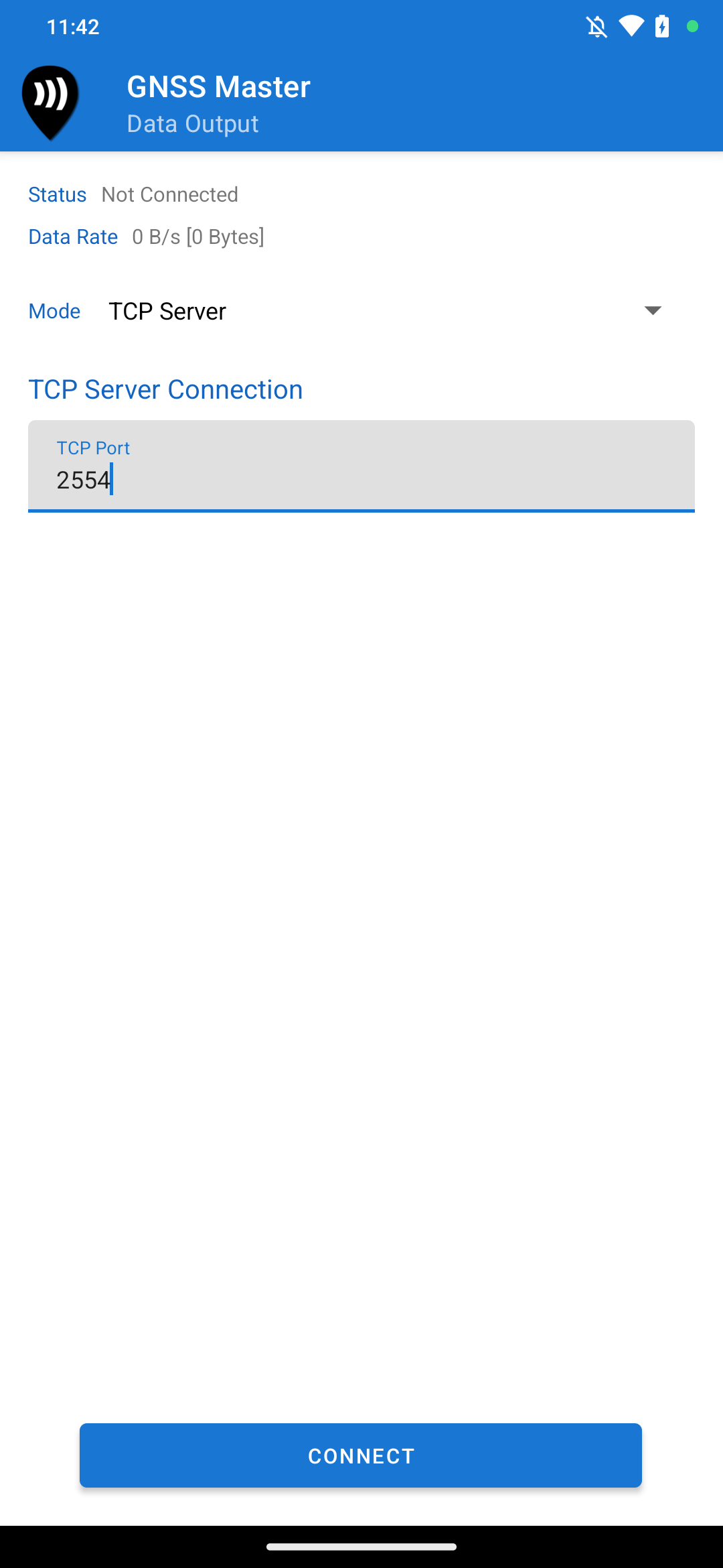
TCP Server Data Output
Mock Location
GNSS Master can be set as the mock location app for Android. Doing so will make all apps installed on the device to use the location from the receiver connected to GNSS Master.
To set up GNSS Master as the mock location provider, you must enable the hidden Developer Mode on your device. Go to Settings->System->About Device and tap on Build Number multiple times to activate developer mode.
Then, go to the Settings->System->Developer Options in settings and scroll down to Select Mock Location App. There, select GNSS Master as the mock location provider.
Once you set GNSS Master as the mock locatio provider, you can enable the Mock Location switch on the Status page.
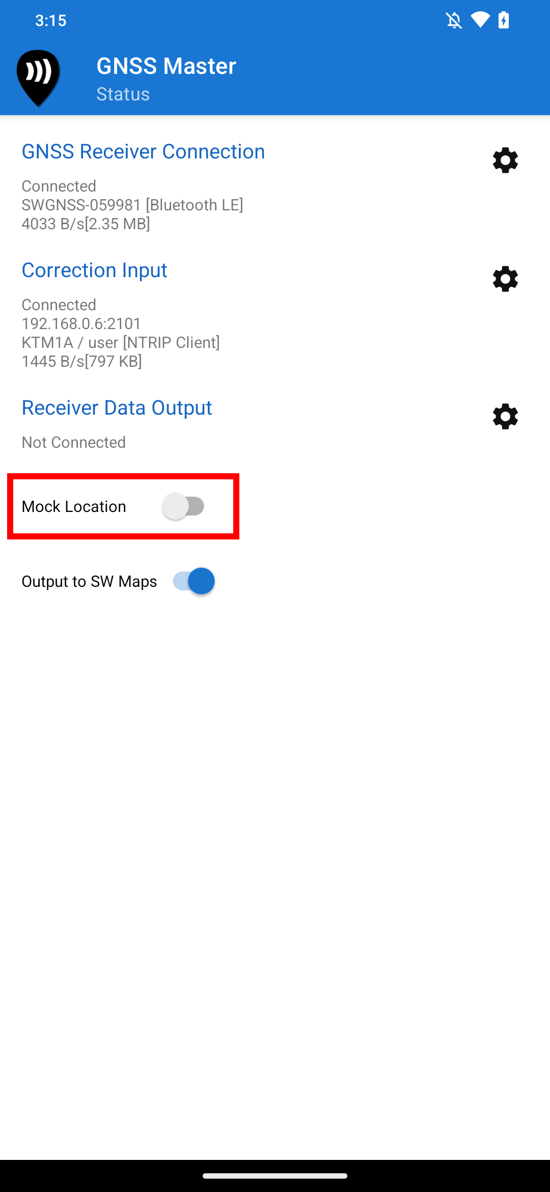
Mock Location Switch
SW Maps Output
GNSS Master supports sending GNSS data to the SW Maps GIS data collector app without enabling mock location. To enable SW Maps Link, turn on the switch in the status page. When enabled, SW Maps will show the instrument name as External App and use the instrument connected to GNSS Master instead of the device internal GNSS receiver.
SW Maps will not use the GNSS Master data output when another instrument is connected to SW Maps via Bluetooth or USB.
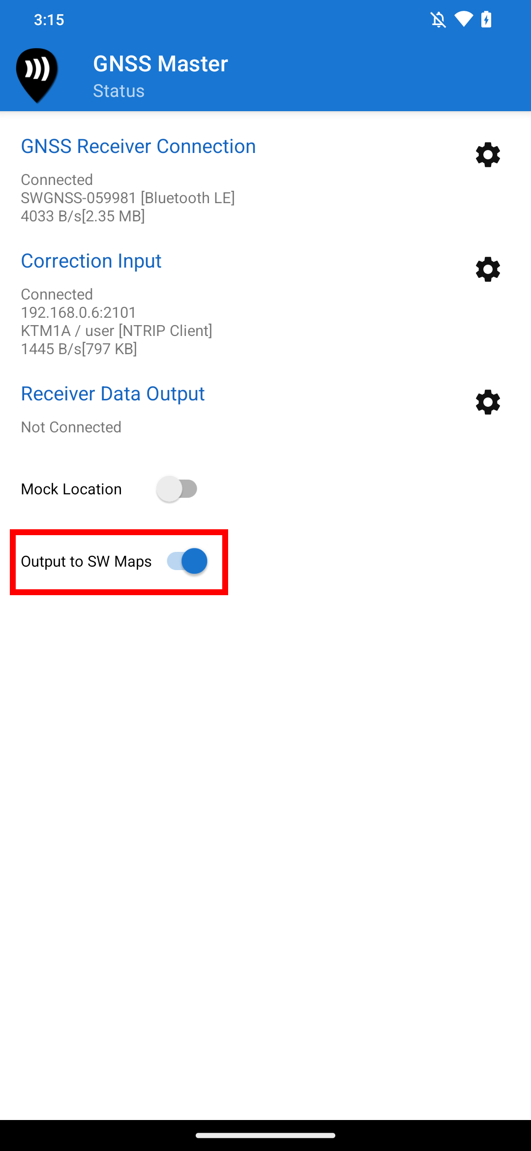
SW Maps Link Switch
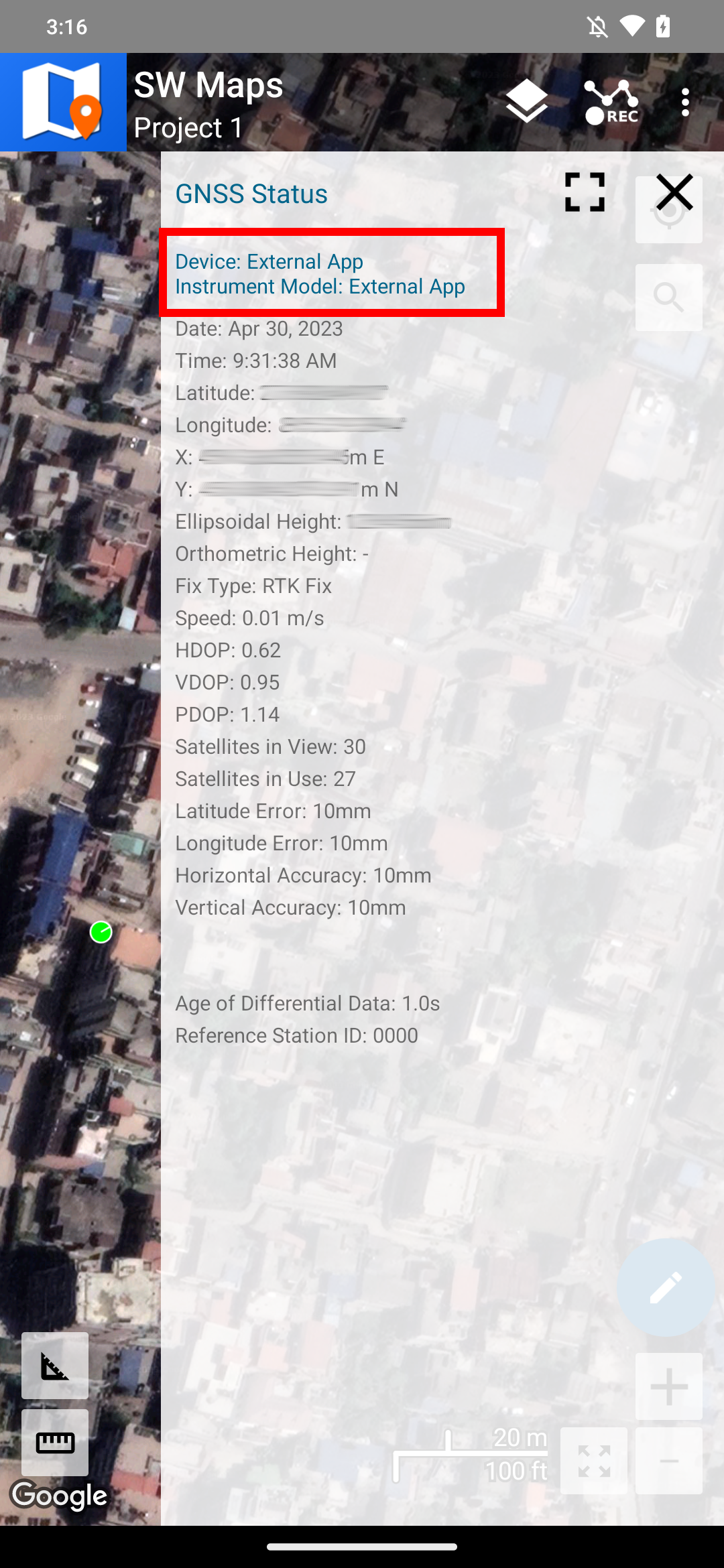
GNSS Master Output in SW Maps as External App instrument
GNSS Status and Skyplot Display
GNSS Master can decode and display the GNSS receiver output. To view the GNSS Status, open the GNSS Status page. The GNSS Status page shows the GNSS position in latitude and longitude, as well as UTM coordinates. It also shows the ellipsoidal height, and the Geoid height above MSL if supported by the connected receiver. Various other information such as DOP, satellites in view and use, and estimated accuracy are also displayed. If the GNSS receiver is receiving differential corrections, the GNSS Status page also shows the age of differential and the reference station ID.
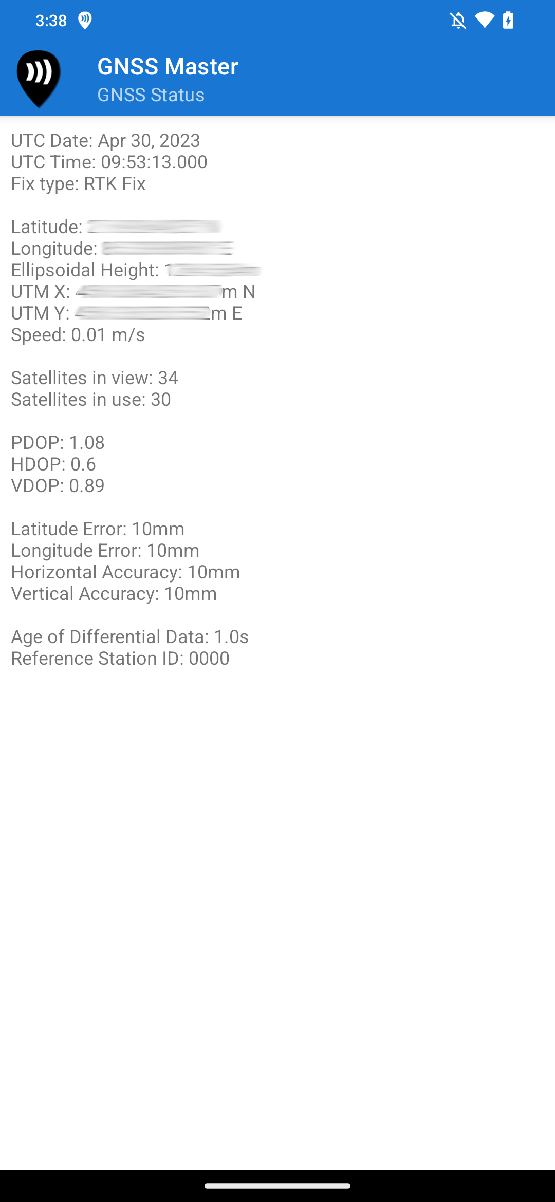
GNSS Status
The Skyplot page shows the satellite skyplot and signal to noise ratios (SNR) of the satellites being received by the connected GNSS receiver.
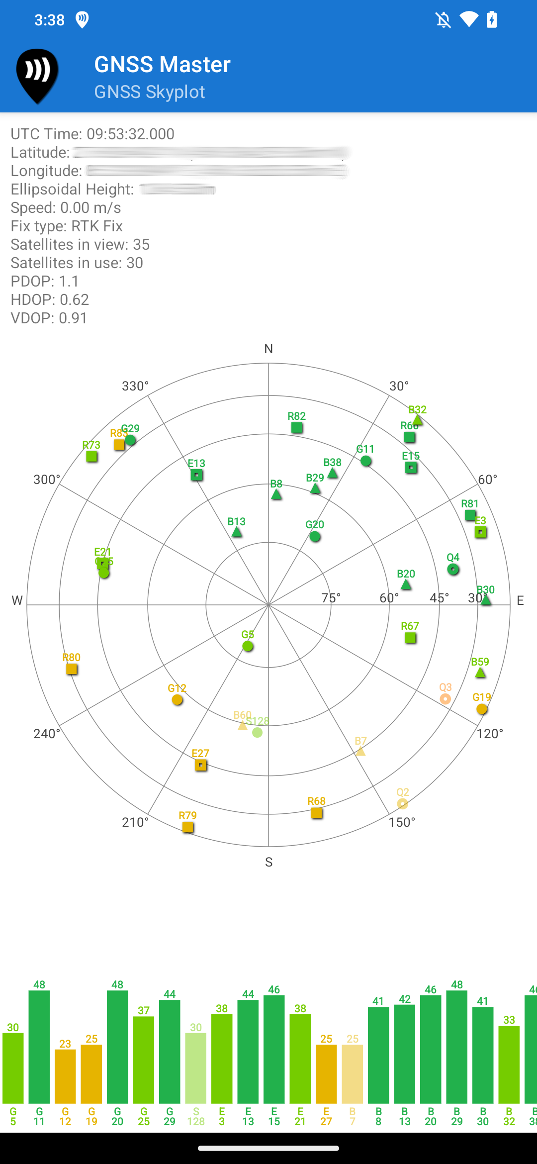
Skyplot
NMEA messages must be enabled in the connected GNSS receiver to view the GNSS Status and Skyplot. Receiver proprietary binary messages are not supported yet. The following NMEA messages are decoded:
-
GGA
-
GSA
-
GSV
-
RMC
-
GST
Receiver Configuration
GNSS Master supports basic configuration of u-blox and Septentrio receivers.
u-blox Configuration
To open the u-blox configuration page, press u-blox Configuration on the left navigation drawer.
Rover Configuration
To set up the receiver in rover mode, set the Receiver Mode to Rover. Then, select a rover rate to output data in, and then press Send Command.
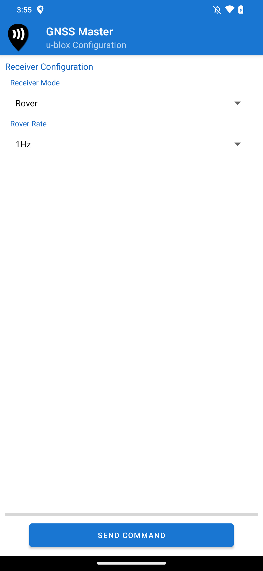
u-blox Rover Configuration
Base Configuration
To set up the receiver in base mode, set the Receiver Mode to Base.
Two different base modes are supported. the Survey In mode sets the base coordinate based on the coordinates computed by the receiver over a certain period of time once a given mimimum accuracy is reached.
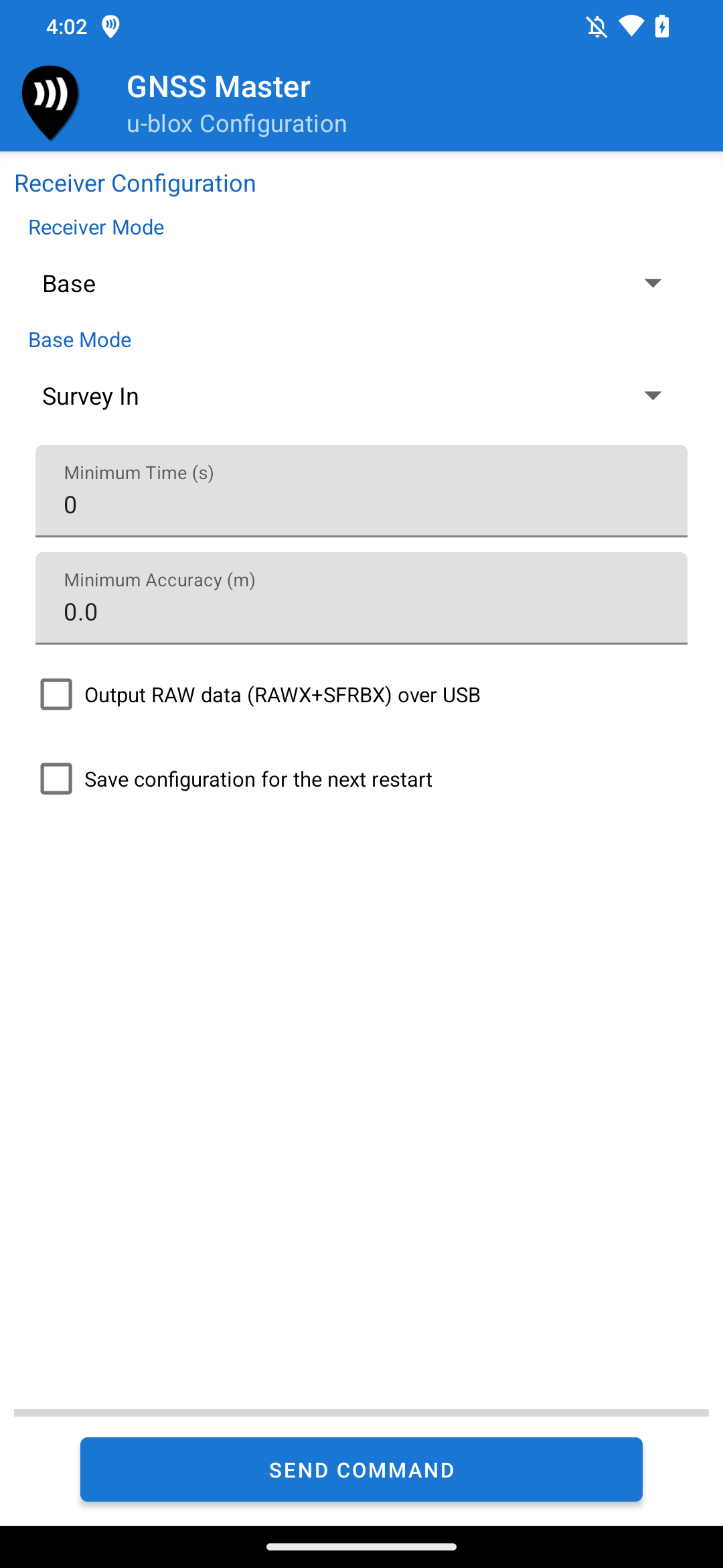
u-blox Base Survey In Configuration
The manual input base configuration lets you enter the base coordinates, either in latitude/longitude or ECEF format.
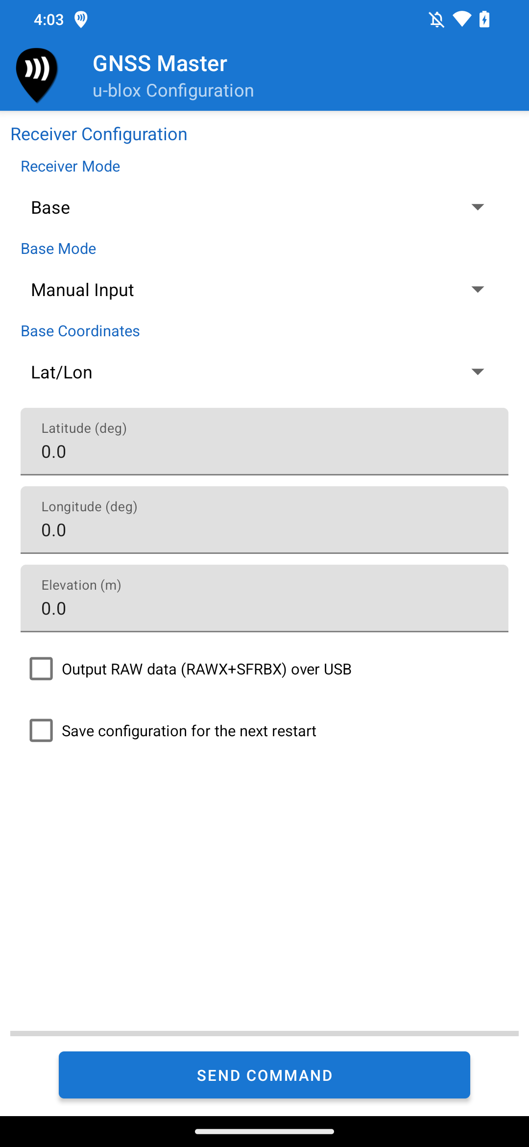
u-blox Base Manual Input Configuration
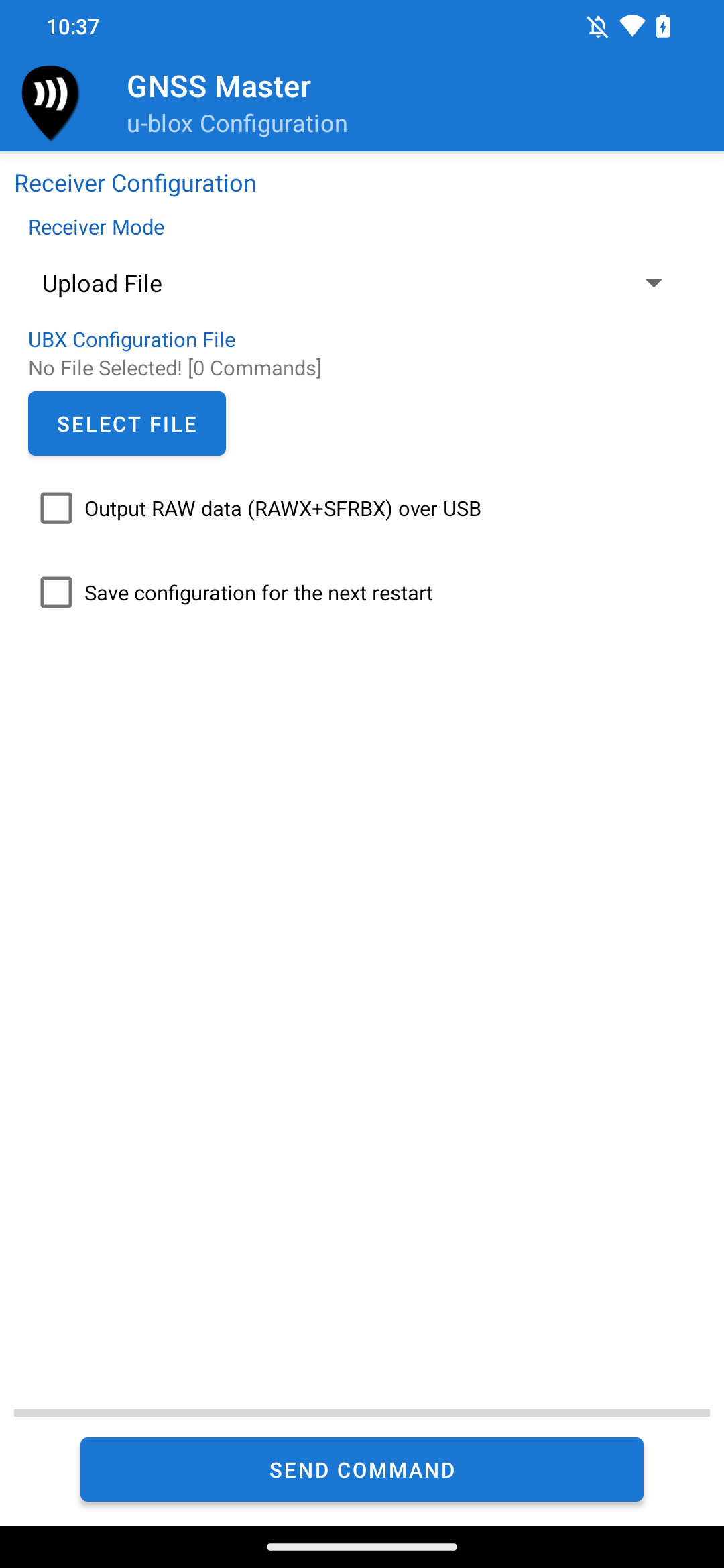
Upload Configuration File
You can also use GNSS Master to upload u-blox configuration files to your receiver. To upload a configuration file, set the Receiver Mode to Upload File.
To upload a configuration file, you must first have the files in your phone or tablet. Configuration files with different presets can be downloaded from ArduSimple.
Then, press the Select File button to pick the configuration file to upload. The selected file and the number of commands found will be displayed. Then, you may upload the file by pressing the Send Command button.
u-blox Configuration File Upload
Additional Options
The Output RAW data (RAWX+SFRBX) over USB enables the output of UBX messages RXM-RAWX and RXM-SFRBX over USB. These messages can be recorded for post processing.
Save configuration for the next restart saves the applied configuration in the receiver flash memory so that the receiver starts up with the same settings when powered on next time.
Septentrio Configuration
To open the Septentrio configuration page, press Septentrio Configuration on the left navigation drawer.
The Septentrio configuration configures the following ports on your Septentrio receiver to output selected messages.
-
COM1
-
COM2
-
COM3
-
USB1
-
USB2
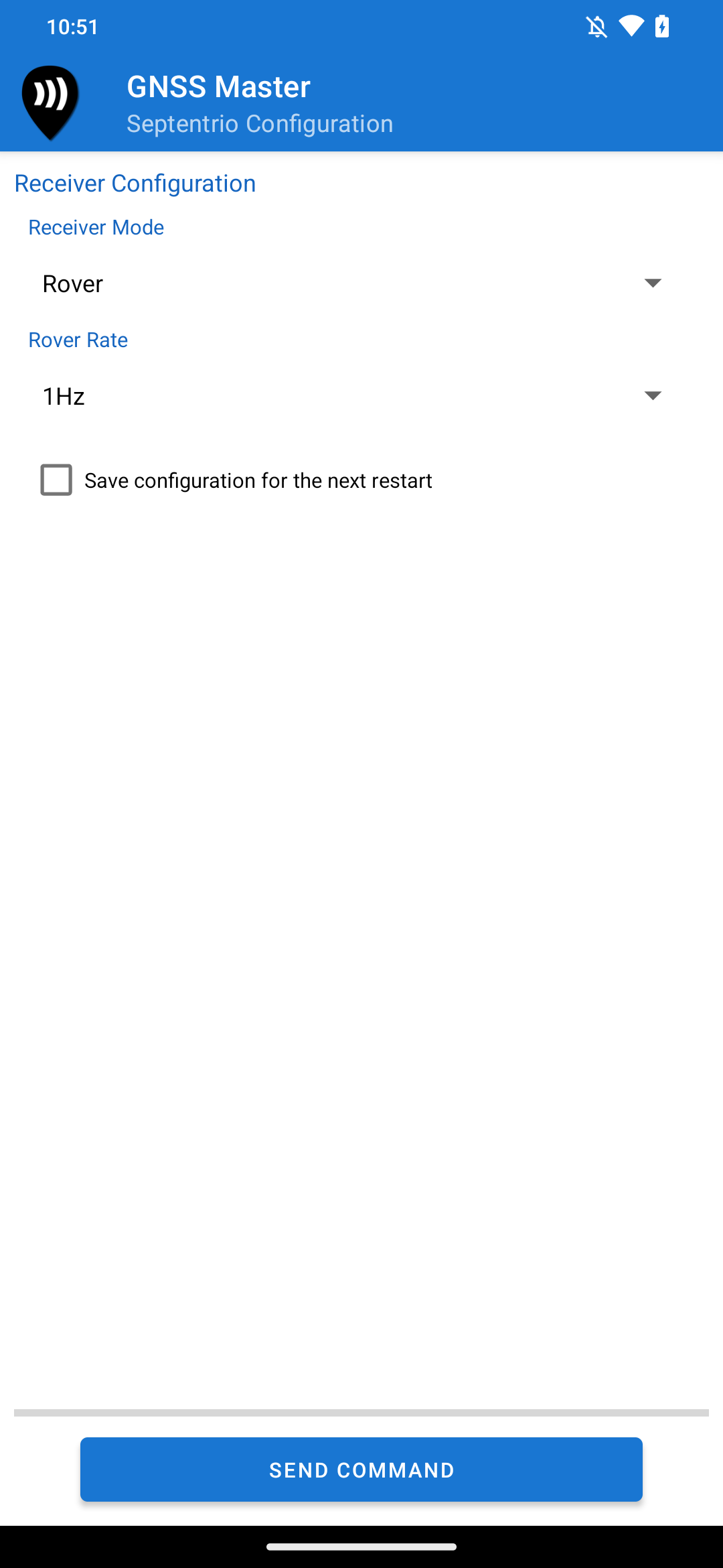
Rover Configuration
To set up the receiver in rover mode, set the Receiver Mode to Rover. Then, select a rover rate to output data in, and then press Send Command.
Rover configuration sets the receiver to output NMEA 4.x messages in the selected ports. The NMEA messages GGA, RMC and GST are output at the selected rover rate, whereas GSA and GSV sentences are always output at 1Hz. The receiver can be configured to output data at the rate of up to 20Hz using GNSS Master.
Septentrio Rover Configuration
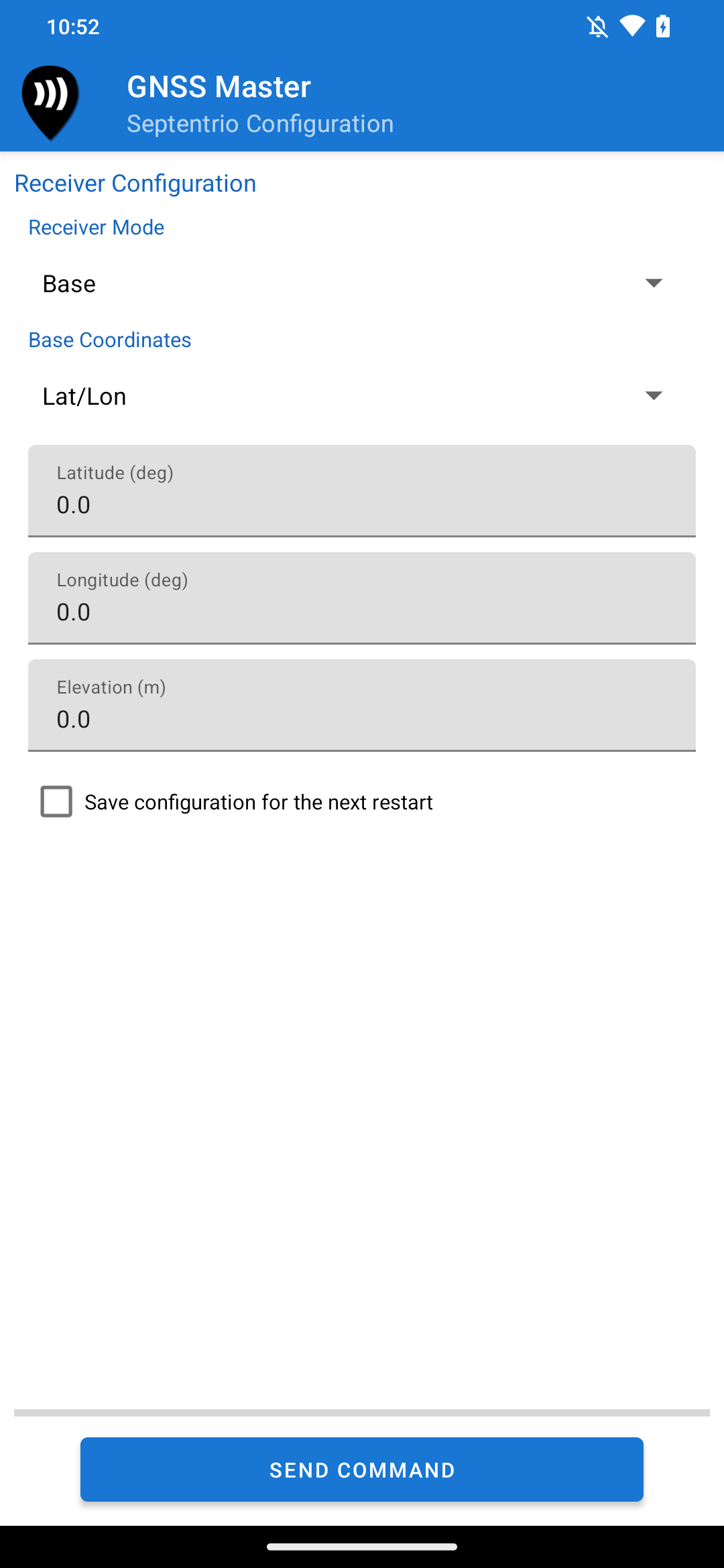
Base Configuration
To set up the receiver in base mode, set the Receiver Mode to Base. The app lets you enter the base coordinates, either in latitude/longitude or ECEF format.
When set in the base configuration, the receiver is configured to output RTCM3 messages in the selected ports. The following RTCM3 messages are output at 1Hz.
-
1006
-
1008
-
1033
-
1230
-
MSM4 (1074, 1084, 1094, 1104, 1114, 1124)
Septentrio Base Configuration